
 English
 Español
 Türk
Türk 中文简体
中文简体
Home / News Room / Industry News / What Makes a Dry-Type Transformer Core Critical to Transformer Efficiency and Reliability?
Content
The core is the magnetic heart of any transformer. In a dry-type transformer — one that uses air or solid resin insulation instead of oil — the core serves as the low-reluctance path through which alternating magnetic flux is channeled between the primary and secondary windings. The efficiency of this energy transfer process is directly governed by the core's material composition, geometric design, lamination quality, and assembly precision. Any compromise in core construction manifests as increased core losses, excessive heat generation, audible noise, or long-term degradation of transformer performance.
Unlike oil-immersed transformers where the core is submerged in dielectric fluid that assists with both cooling and insulation, dry-type transformer cores must be engineered to dissipate heat through convective air cooling alone. This places more stringent demands on core material selection and design, making a thorough understanding of dry-type transformer core technology essential for engineers, procurement specialists, and facility managers responsible for specifying or maintaining electrical distribution equipment.
The vast majority of dry-type transformer cores are constructed from cold-rolled grain-oriented (CRGO) silicon steel, also known as electrical steel. This material is specifically engineered to exhibit low hysteresis loss and low eddy current loss — the two primary components of core loss in alternating current applications. Silicon steel contains between 2% and 4% silicon by weight, which significantly increases electrical resistivity compared to plain carbon steel, thereby reducing eddy current circulation within the laminations.
CRGO silicon steel is processed so that its grain structure is aligned along the rolling direction, which is also the direction of magnetic flux flow in the assembled core. This grain orientation reduces the energy required to magnetize the material in the flux direction, resulting in lower core losses and higher magnetic permeability. CRGO steel is the standard material for distribution and power transformer cores globally, with grades designated by their maximum core loss values at specified flux densities (e.g., M4, M5, M6 per ASTM standards).
Advanced grades of CRGO steel, including high-permeability (Hi-B) and laser-scribed domain-refined variants, offer further reductions in core loss — typically 10–20% lower than standard CRGO at equivalent flux densities. These premium materials are used in high-efficiency transformer designs where no-load loss minimization is a key design objective, such as in transformers subject to efficiency regulations like DOE 2016 in the United States or EU Tier 2 standards in Europe.
Amorphous metal alloys — produced by rapidly quenching molten metal to prevent crystalline structure formation — exhibit exceptionally low core losses, typically 70–80% lower than conventional CRGO silicon steel. Amorphous core transformers are increasingly specified in energy-efficiency-focused applications, particularly in distribution networks where transformers operate continuously at partial load. The trade-off is that amorphous metal is more brittle and harder to process than silicon steel, which increases manufacturing complexity and cost.
To minimize eddy current losses, transformer cores are not constructed from solid blocks of metal. Instead, the core material is cut or slit into thin laminations — typically 0.23 mm to 0.35 mm thick for CRGO steel — which are electrically insulated from one another by a thin oxide layer or applied coating. Each lamination presents a high-resistance barrier to circulating eddy currents, confining them to a small cross-sectional area and dramatically reducing I²R losses within the core material.
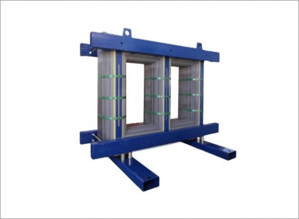
In traditional stacked core designs, individual lamination sheets are cut to shape and stacked in alternating layers with offset joints at the corners. The step-lap joint configuration — where joints are distributed across multiple laminations rather than aligned at a single point — significantly reduces localized flux crowding and associated loss spikes at corner joints. Stacked cores are versatile and suitable for both single-phase and three-phase transformer configurations.
Wound cores are formed by continuously winding a strip of grain-oriented silicon steel into a closed loop, eliminating the need for cut joints at corners. Because the magnetic flux path always follows the grain direction of the material, wound cores achieve lower core losses and produce less audible noise compared to equivalent stacked core designs. Toroidal wound cores are commonly used in single-phase dry-type transformers for sensitive electronic and instrumentation applications where noise and stray magnetic field minimization are critical.
Dry-type transformer cores are designed in two primary geometric configurations, each offering distinct advantages depending on the application requirements.
| Feature | Core-Type Design | Shell-Type Design |
| Winding Arrangement | Windings surround the core limbs | Core surrounds the windings |
| Flux Path | Single magnetic circuit | Divided magnetic circuit |
| Heat Dissipation | Good — windings exposed to airflow | Moderate — windings enclosed |
| Mechanical Strength | Moderate | High — core provides bracing |
| Common Use | Distribution transformers, most dry-type units | High-current, low-voltage applications |
| Manufacturing Complexity | Lower | Higher |
Core-type construction dominates the dry-type transformer market due to its simplicity, effective thermal performance through natural air convection, and ease of inspection and maintenance. Shell-type designs are reserved for specialized applications requiring enhanced mechanical robustness or specific electromagnetic shielding characteristics.
Core losses — also referred to as no-load losses or iron losses — are present whenever the transformer is energized, regardless of whether it is supplying load current. They represent a continuous energy drain on the electrical system and are a primary factor in lifetime operating cost calculations for transformers. Core losses consist of two components:
In practical transformer design, the balance between core loss and copper loss (load-dependent winding resistance losses) is optimized based on the expected load profile. Transformers that operate continuously at or near full load are designed to minimize copper losses, while those that remain energized at light or no load for extended periods benefit most from minimized core losses through premium core materials.
Audible noise from dry-type transformers is primarily generated by magnetostriction — the cyclic dimensional change of the core laminations as they are magnetized and demagnetized at twice the supply frequency (100 Hz for 50 Hz systems, 120 Hz for 60 Hz systems). This mechanical vibration is transmitted through the core structure and can be amplified by resonance with the transformer enclosure or building structure. Noise is a significant concern for dry-type transformers installed in occupied buildings such as hospitals, schools, offices, and data centers.
Design measures to reduce core noise include operating at lower flux density — which reduces the magnitude of magnetostrictive strain — using step-lap joint construction to minimize flux turbulence at lamination interfaces, applying vibration-damping materials between the core and mounting structure, and selecting high-permeability core materials that achieve the required flux density at lower magnetic field strength. The sound level of a transformer core is specified in decibels (dB) and must comply with NEMA ST-20 or IEC 60076-10 standards for installation in noise-sensitive environments.
After lamination assembly, the dry-type transformer core is mechanically clamped using steel frames, bolts, or banding to maintain dimensional stability under the cyclic magnetic forces experienced during operation. Inadequate clamping allows laminations to vibrate independently, increasing noise levels and causing progressive mechanical wear at lamination interfaces that degrades insulation coatings over time.
The assembled core is typically treated with a moisture-resistant varnish or epoxy coating to prevent corrosion of the exposed steel edges and to consolidate the lamination stack. For transformers installed in humid, corrosive, or tropical environments, more robust protective treatments including epoxy encapsulation of core edges or stainless-steel banding may be specified. These treatments also contribute to the overall dielectric integrity of the transformer assembly by preventing conductive particle contamination from loose lamination edges.
Specifying a dry-type transformer core correctly requires a clear understanding of the operating conditions, efficiency requirements, installation environment, and applicable standards. Key parameters to define during the specification process include:
Engaging with transformer manufacturers early in the design or procurement process allows core specifications to be optimized for total cost of ownership rather than purchase price alone. Given that a distribution transformer may remain in continuous service for 25–40 years, even modest improvements in core loss performance translate into substantial cumulative energy savings and a measurably lower carbon footprint over the asset's operating lifetime.
 +86-523 8891 6699
  +86-523 8891 8266
  info@tl-core.com
  No.1, Third Industrial Park, Liangxu Street, Taizhou City, Jiangsu, China
 Copyright © 2024 Taizhou Tianli Iron Core Manufacturing Co., Ltd. All Rights Reserved.


