
 English
 Español
 Türk
Türk 中文简体
中文简体
Home / News Room / Industry News / How Do You Check a Power Distribution Transformer Core — and What Are the Warning Signs?
Content
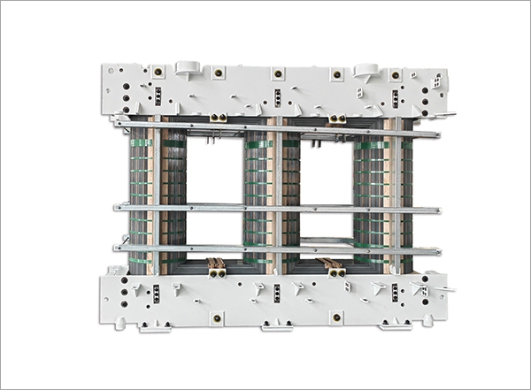
The power distribution transformer core is the magnetic heart of one of the most critical components in any electrical distribution network. Whether installed in a utility substation, an industrial facility, or a commercial building power room, the transformer core performs the fundamental function of transferring electrical energy between primary and secondary windings through magnetic flux — and its condition directly determines the transformer's efficiency, thermal performance, and service life. Checking a transformer, and specifically evaluating the health of its core, is a structured process that combines visual inspection, electrical testing, and oil analysis into a coherent picture of the unit's current condition and remaining service life. This article covers how to check a power distribution transformer correctly, what the core's role is in transformer health, and what specific test results indicate developing problems before they become failures.
The transformer core is a stack of thin laminated silicon steel sheets — typically 0.23 mm to 0.35 mm thick — assembled into a specific geometric form (core-type or shell-type) that provides a low-reluctance magnetic path for the alternating flux generated by the primary winding. Each lamination is coated with a thin insulating varnish or oxide layer that prevents eddy currents from flowing between adjacent sheets. Without this lamination, the alternating magnetic field would induce large circulating currents within a solid steel core, converting electrical energy into heat rather than useful magnetic flux — an effect called eddy current loss that would make the transformer thermally unacceptable and extremely inefficient.
In addition to eddy current losses, transformer cores are subject to hysteresis losses — energy dissipated as heat each time the magnetic domains within the silicon steel are realigned by the alternating field, which occurs 50 or 60 times per second continuously throughout the transformer's operating life. Modern grain-oriented silicon steel cores are manufactured with carefully controlled crystal orientation to minimize hysteresis losses, but the cumulative effect of decades of magnetic cycling, thermal stress, and mechanical vibration gradually degrades the core lamination insulation, shifts lamination alignment, and can produce progressive increases in core loss that reduce transformer efficiency and increase operating temperature. Understanding this degradation mechanism is the foundation for understanding why regular testing of the core's electrical parameters matters so much in transformer maintenance programs.
Before performing any electrical testing, a thorough visual and physical inspection of the transformer provides qualitative information that guides the scope and urgency of subsequent electrical tests. For oil-filled distribution transformers, visual inspection covers both the external tank assembly and, where access permits during maintenance outages, the core and coil assembly.
Electrical testing of a power distribution transformer provides quantitative data on the condition of the core, windings, and insulation system. The following tests are specifically relevant to evaluating core condition and should be part of any comprehensive transformer inspection program.
The core insulation resistance test — also called the core ground test or core megger test — measures the insulation resistance between the transformer core and the tank (ground). On a healthy transformer, the core is insulated from the tank everywhere except at the single intentional grounding point. The test is performed by isolating the core ground lead (if the transformer design brings it out to an external terminal), applying a DC test voltage (typically 500 V or 1,000 V from an insulation resistance meter — a "megger"), and measuring the resulting resistance. A healthy core will typically show insulation resistance values in the range of hundreds of megaohms to several gigaohms. Values below 1 MΩ indicate a fault — either a second unintended core-to-tank contact point (a "shorted core" condition) or severe moisture contamination in the core lamination insulation. Shorted cores cause circulating currents that generate localized heating detectable by thermal imaging or dissolved gas analysis but not always by winding resistance or turns ratio testing alone.
The no-load loss test — also called the excitation loss or iron loss test — measures the power consumed by the transformer core when rated voltage is applied to the primary winding with the secondary open-circuited. Under no-load conditions, the only power drawn from the supply goes into overcoming the core's hysteresis and eddy current losses, plus a small amount of copper loss in the primary winding (which is subtracted or negligible at rated voltage). The no-load loss is measured in watts or kilowatts and compared to the manufacturer's factory test report value for the same unit. An increase in no-load loss above the factory baseline of more than 10 to 15% indicates core deterioration — typically from inter-laminar insulation breakdown causing increased eddy current paths, or from core damage that has altered the flux distribution within the core. This test requires energizing the transformer at rated voltage and frequency, so it is performed during scheduled maintenance outages when the transformer can be connected to a power supply while remaining isolated from the distribution network load.
The excitation current test is performed simultaneously with the no-load loss test and measures the current drawn by each phase of the primary winding under rated voltage no-load conditions. The excitation current (also called magnetizing current) represents the current required to establish the magnetic flux in the core. In a healthy three-phase transformer, the excitation current in the outer limbs (legs) of the core is typically higher than in the center limb due to the asymmetry of the core magnetic path lengths — an expected and normal pattern. Significant asymmetry beyond the expected pattern, or a marked increase in excitation current on one or more phases compared to factory baseline values, can indicate localized core damage, shorted turns in the primary winding, or physical damage to the core geometry from transportation or seismic events. Comparing test results to the original factory test report is essential for meaningful interpretation — excitation current values in isolation have limited diagnostic value without the baseline reference.
Dissolved Gas Analysis of the transformer insulating oil is the single most powerful diagnostic tool for detecting developing faults in oil-filled distribution transformers, including core-related faults. When abnormal thermal or electrical activity occurs within the transformer tank — whether from shorted core laminations, partial discharge, arcing, or winding faults — the energy decomposes the surrounding insulating oil and cellulose insulation into characteristic gas mixtures. These gases dissolve in the oil and can be extracted and quantified by laboratory analysis of an oil sample.
| Gas | Primary Source | Fault Indication |
| Hydrogen (H₂) | Oil decomposition | Partial discharge, corona, low-energy arcing |
| Methane (CH₄) | Oil decomposition | Thermal faults (low temperature) |
| Ethylene (C₂H₄) | Oil decomposition | Thermal faults (high temperature, >300°C) |
| Acetylene (C₂H₂) | Oil decomposition | High-energy arcing (>700°C) — urgent fault |
| Carbon Monoxide (CO) | Cellulose decomposition | Thermal degradation of paper insulation |
| Carbon Dioxide (CO₂) | Cellulose decomposition | Normal aging or overheating of paper insulation |
For core-specific fault detection, elevated hydrogen and methane with moderate ethylene — the pattern associated with thermal faults at relatively low temperatures — is the characteristic signature of shorted core laminations generating localized hot spots in the oil. The IEC 60599 and IEEE C57.104 standards provide interpretation frameworks (including the Duval Triangle and key gas ratio methods) for diagnosing fault type from DGA results. Trending DGA results over time — comparing current results against previous samples — is more diagnostically valuable than a single sample, because the rate of gas generation is as informative as the absolute gas concentrations in identifying active versus historical faults.
While the core-specific tests above address the transformer core directly, a complete assessment of how to check a transformer requires additional tests that evaluate the winding and insulation system alongside the core. These tests provide complementary diagnostic information and are standard components of any comprehensive transformer inspection.
Insulation resistance testing of the windings measures the DC resistance between the high-voltage and low-voltage windings and between each winding and ground (the tank). Tests are conducted using an insulation resistance meter at 2,500 V or 5,000 V for medium and high-voltage distribution transformers. The Polarization Index (PI) — the ratio of the 10-minute insulation resistance reading to the 1-minute reading — provides a more robust indicator of insulation condition than a single-point resistance value, because it reflects the dielectric absorption characteristics of the insulation rather than just its instantaneous resistance. A PI of 2.0 or above generally indicates acceptable insulation condition; values below 1.5 suggest moisture contamination or significant insulation degradation requiring further investigation before returning the transformer to service.
The turns ratio test verifies that the ratio of primary to secondary turns — and therefore the transformer's voltage transformation ratio — matches the nameplate specification within acceptable tolerance (typically ±0.5% for distribution transformers). The test is conducted using a transformer turns ratio (TTR) meter that applies a low-voltage AC signal to the primary winding and measures the resulting secondary voltage, computing the turns ratio directly. Deviation from the nameplate ratio indicates shorted turns in either the primary or secondary winding — a condition that increases winding copper losses, reduces voltage regulation performance, and if progressive, will eventually lead to thermal failure of the shorted turn region. Turns ratio testing is quick and non-destructive, and it provides a definitive check on winding integrity that complements the insulation resistance and DGA data.
Measuring the DC resistance of each winding at a known temperature and comparing against factory test data (corrected to the same reference temperature) identifies high-resistance connections at tap changer contacts, lead connections, or bushing terminals, as well as open-circuit conditions in parallel winding paths. DC resistance measurements are typically made using a precision micro-ohmmeter capable of measuring milliohm-level resistances accurately. Resistance increases of more than 2 to 3% above the corrected baseline in any phase indicate developing connection problems that will generate heat under load and, if not addressed, lead to connection failure or thermal damage to adjacent insulation.
The frequency and scope of transformer testing should be determined by the unit's criticality, age, loading history, environmental exposure, and the results of previous inspections. The following framework provides a practical starting point for scheduling distribution transformer inspections.
Checking a power distribution transformer — and specifically evaluating the health of its core — is not a single-test exercise but a structured diagnostic process that combines visual inspection, targeted electrical testing, and oil analysis into a coherent picture of the unit's condition. Each test addresses a specific failure mode or degradation mechanism, and the combination of results from core insulation resistance, no-load loss, excitation current, DGA, and winding tests provides the comprehensive data needed to make informed decisions about maintenance priority, load management, and remaining service life. Applied systematically and consistently over the transformer's operating life, this testing program is the most effective investment available for protecting the reliability and longevity of one of the most capital-intensive components in any electrical distribution system.
 +86-523 8891 6699
  +86-523 8891 8266
  info@tl-core.com
  No.1, Third Industrial Park, Liangxu Street, Taizhou City, Jiangsu, China
 Copyright © 2024 Taizhou Tianli Iron Core Manufacturing Co., Ltd. All Rights Reserved.


