Content
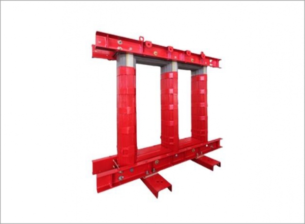
A dry-type transformer core is the magnetic circuit at the center of a dry-type transformer — a power transformer that uses air or solid resin insulation for cooling rather than the mineral oil used in liquid-filled transformers. The core itself is constructed from thin laminations of grain-oriented silicon steel, each coated with an insulating varnish or oxide layer to prevent eddy currents from circulating between laminations. These laminations are stacked and interleaved in either a shell-type or core-type configuration, forming a closed magnetic path that guides the alternating magnetic flux generated by the primary winding through the secondary winding with minimal energy loss. The quality of the core material — its silicon content, lamination thickness, and grain orientation — directly determines the transformer's no-load losses, magnetizing current, and overall efficiency, which is why premium dry-type transformers use high-grade M3 or M5 silicon steel in their core construction.
In a core-type transformer, the windings surround the core limbs — the primary and secondary coils are wound concentrically around the same core leg or on separate legs, depending on the design. In a shell-type configuration, the core surrounds the windings, enclosing them on multiple sides and providing better mechanical protection but requiring more core material per unit of power capacity. For most commercial and industrial dry-type transformers in the 10 kVA to 3,000 kVA range, the core-type design is standard because it is more economical to manufacture, easier to inspect, and simpler to wind. The windings of a dry-type transformer use either aluminum or copper conductors insulated with polyester film, nomex paper, or epoxy resin depending on the insulation class — Class F (155°C) and Class H (180°C) are the most common thermal classifications for industrial dry-type units.
The absence of oil in dry-type transformers makes them inherently safer for indoor installation in occupied buildings, tunnels, offshore platforms, and other environments where an oil spill or fire would be catastrophic. They require no oil containment bunding, no Buchholz relay protection, and no periodic oil sampling — maintenance requirements are limited to periodic inspection of the windings, core, and electrical connections, plus cleaning of ventilation openings to ensure adequate airflow for cooling. These characteristics make dry-type transformers the default choice for building distribution transformers, data center power infrastructure, renewable energy inverter step-up applications, and anywhere that environmental safety or fire risk is a governing design constraint.
Not all dry-type transformer cores are constructed identically, and the differences between core types affect both the transformer's electrical performance and the physical configuration of its winding terminals — which in turn affects how the transformer is wired into a power distribution system.
A single-phase dry-type transformer has a core with two limbs — one for each winding half — or a single central limb with the windings concentrated there and return flux paths on either side. Single-phase transformers produce two winding terminals on the primary side (labeled H1 and H2) and two on the secondary side (labeled X1 and X2) as standard. For transformers with center-tapped secondary windings — common in 120/240V residential and commercial applications — a third terminal (X2 at the center tap) is provided, enabling both 120V single-phase and 240V single-phase loads to be served from the same transformer. Understanding the core configuration helps the installer correctly interpret the nameplate and terminal marking scheme before attempting any wiring connection.
Three-phase dry-type transformers use a three-limb or five-limb core on which the three phases of primary and secondary windings are mounted. The three-limb core — by far the most common design — places one phase winding on each of the three core legs, with the magnetic flux of the three phases summing to zero in the core under balanced load conditions, eliminating the need for a return flux path and keeping the core compact. Five-limb cores are used for very large transformers or applications requiring specific zero-sequence impedance characteristics. Three-phase transformer terminal markings follow standardized designations: primary terminals are labeled H1, H2, H3 (and H0 for neutral if accessible), while secondary terminals are labeled X1, X2, X3 (and X0 for neutral). The arrangement of these terminals on the transformer's terminal board — which may be organized differently between manufacturers — must be confirmed from the nameplate diagram before wiring begins.
Before physically wiring a dry-type transformer, it is essential to understand the winding configuration specified on the nameplate and what it means for the connection scheme. Wiring a transformer incorrectly — connecting the wrong voltage taps, using an incompatible delta or wye configuration, or reversing polarity — can result in equipment damage, protection system failure, or a dangerous overvoltage condition on the secondary circuit. The most common winding configurations encountered in dry-type distribution transformers are summarized in the table below:
| Configuration | Primary | Secondary | Typical Application |
| Delta–Wye (Δ–Y) | Delta (no neutral) | Wye (neutral available) | Step-down distribution, building power |
| Wye–Delta (Y–Δ) | Wye (neutral available) | Delta (no neutral) | Step-up for motor loads, industrial |
| Wye–Wye (Y–Y) | Wye | Wye | Low-voltage distribution with neutral |
| Delta–Delta (Δ–Δ) | Delta | Delta | Industrial motor drives, no neutral needed |
| Single-Phase Center Tap | H1–H2 | X1–X2–X3 (center tapped) | 120/240V residential, control circuits |
Wiring a dry-type transformer requires methodical preparation, strict adherence to safety procedures, and careful verification at each stage before energization. The following process applies to connecting a three-phase dry-type distribution transformer in a commercial or industrial installation, though the same principles apply to single-phase units with simpler terminal arrangements.
Before any wiring work begins, locate the transformer nameplate and verify that the rated primary voltage matches the supply voltage available at the installation point. Dry-type transformers are typically supplied with multiple primary voltage taps — commonly ±2.5% and ±5% of the nominal voltage — to accommodate supply voltage variations common in utility distribution systems. Confirm which tap position corresponds to your actual supply voltage and identify the corresponding H1, H2, H3 terminal assignments for that tap. Misidentifying tap terminals is a common cause of secondary overvoltage or undervoltage after commissioning. Also verify the rated secondary voltage, the KVA capacity, the frequency rating, and the insulation class against the installation design requirements.
Transformer wiring must never be performed on energized equipment under any circumstances. Before beginning work, open and lock out the upstream supply breaker or disconnect switch serving the transformer's primary circuit, and apply a personal lockout tag clearly identifying the person performing the work and the reason for lockout. Test all primary terminals with an appropriate voltage tester to confirm the absence of voltage before touching any terminal. For transformers with capacitor banks or long cable runs that may hold residual charge, apply temporary earthing/grounding conductors to all primary and secondary terminals using insulated earthing sticks before allowing physical contact with the terminal board. These lockout and earthing procedures are mandatory safety requirements — skipping them even briefly to "save time" creates an immediate risk of fatal electrocution.
Connect the incoming supply conductors to the primary terminals according to the nameplate wiring diagram. For a delta-connected primary, connect Phase A to H1, Phase B to H2, and Phase C to H3, with the delta loop closed by the internal connections within the transformer's terminal board as specified on the diagram. For a wye-connected primary, connect the three phase conductors to H1, H2, and H3 respectively, and connect the neutral conductor to H0 if provided. If voltage tap links are present on the primary terminal board — small copper bars or bolts that connect alternate tap terminals — verify that they are correctly positioned for the selected tap voltage before completing primary wiring. Use correctly rated ring-tongue cable lugs on the primary conductors, torque all terminal bolts to the manufacturer's specified torque value, and verify that no bare conductor is exposed outside the lug barrel or terminal clamp.
Secondary terminal connections follow the same basic procedure as primary connections but at lower voltage and typically higher current — which means larger conductor cross-sections, heavier lugs, and potentially multiple parallel conductors per terminal for large transformers. Connect the secondary phase conductors to X1, X2, and X3 according to the nameplate diagram and the downstream distribution panel's phase labeling convention. For wye-connected secondaries, connect the neutral conductor to X0 (or the center point of the wye formed at the terminal board). The transformer's secondary neutral point should be grounded to the building grounding electrode system in accordance with local electrical codes — typically NEC Article 250 in the United States or the equivalent national standard — using a grounding conductor of appropriate size for the transformer's secondary current rating. Verify phase rotation at the secondary terminals using a phase sequence indicator before connecting the transformer to the downstream distribution panel, as incorrect phase rotation can reverse motor direction and damage phase-sensitive equipment.
The transformer's steel enclosure, core, and frame must be bonded to the facility grounding system to ensure that any fault voltage reaching the enclosure is safely conducted to ground rather than presenting a shock hazard to personnel. Connect an equipment grounding conductor from the transformer's ground lug — typically a dedicated bolt on the enclosure with a green ground symbol — to the facility ground bus or grounding electrode conductor. The size of this grounding conductor is determined by the transformer's secondary overcurrent protection rating, not by the transformer's KVA rating, and must comply with the applicable electrical code. Verify that the grounding conductor is continuous, mechanically secure, and makes clean metal-to-metal contact at both ends without paint, oxide, or other high-resistance contamination at the connection points.
Many dry-type transformers — particularly control and isolation transformers used in industrial machine control panels — are designed with multiple secondary winding sections that can be connected in series or parallel to produce different output voltages from the same transformer core. Understanding how to wire these multi-winding configurations correctly is essential for control panel builders and machine wiring technicians.
A control transformer with dual secondary sections, each rated at 120V, can produce 240V by connecting the two sections in series — connecting the X2 terminal of the first section to the X3 terminal of the second section, with the output voltage measured between X1 of the first section and X4 of the second. Alternatively, the same transformer produces 120V at doubled current capacity by connecting the sections in parallel — connecting X1 to X3 and X2 to X4, with the load connected across the X1/X3 junction and the X2/X4 junction. In both configurations, the additive polarity of the two sections must be confirmed before making the series or parallel connection — connecting the sections in subtractive polarity in a series configuration produces zero output voltage, and in a parallel configuration causes a short circuit within the transformer. The nameplate wiring diagram always shows the correct polarity connections for each configuration, and these must be followed exactly rather than inferred from visual inspection of the terminal board.
Several categories of wiring errors recur consistently in transformer installation practice, and awareness of these mistakes allows installers to apply extra care at the specific points where errors are most likely to occur.
Before removing the lockout/tagout and energizing a newly wired dry-type transformer, a systematic pre-energization verification checklist should be completed to confirm that the installation is correct and safe for initial energization. Rushing this step is one of the most common causes of equipment damage and safety incidents during transformer commissioning.
Wiring a dry-type transformer correctly requires understanding the core's magnetic function, interpreting the nameplate winding configuration accurately, following a disciplined safety lockout procedure throughout, and completing systematic pre-energization verification before the transformer is placed into service. Each of these steps builds directly on the previous one — skipping or rushing any stage creates risks that compound toward equipment failure or personnel injury. For electrical professionals and facility maintenance technicians alike, treating transformer wiring as a precision task governed by engineering data rather than a routine connection job is the foundation of safe, reliable transformer installations that serve their intended service life without incident.
 +86-523 8891 6699
  +86-523 8891 8266
  info@tl-core.com
  No.1, Third Industrial Park, Liangxu Street, Taizhou City, Jiangsu, China
 Copyright © 2024 Taizhou Tianli Iron Core Manufacturing Co., Ltd. All Rights Reserved.


 English
 Español
 Türk
Türk 中文简体
中文简体


